Wind Vane & Wind Direction Sensor
Professional wind direction measurement for weather surveillance networks — delivering continuous 0–360° directional data, storm-front wind shift detection, smoke and plume tracking, and multi-sensor integration for emergency management, outdoor safety, industrial operations, and environmental monitoring.
Contents
01 The Instrument — What a Wind Vane Measures and Why It Matters
02 Wind Direction — Definitions, Conventions, and What Direction Tells You
03 How Wind Vanes Work — From Weathercock to Digital Sensor
04 Sensor Technology — Mechanical Vane vs. Ultrasonic Wind Direction
05 Vector Averaging — Why Wind Direction Averaging Requires Special Math
06 Siting & Mounting — The WMO 10-Meter Standard and Why It Matters
07 Operational Applications
08 Instrument Selection Guide
09 Installation & Maintenance
10 cyclonePort Wind Direction System — Platform, Integration & Deployment
11 Frequently Asked Questions


- 2–3°
- 0–360°, no dead zone
- 1°
- RadarOmega
01 The Instrument — What a Wind Vane Measures and Why It Matters
A wind vane — also called a wind direction sensor, wind direction indicator, weather vane, or anemoscope — is the instrument that measures the compass bearing from which the wind is blowing. Wind direction is one of the two fundamental wind measurements (alongside wind speed), and it carries distinct meteorological intelligence that speed alone cannot provide: it tells you where the air mass is coming from, what weather it is carrying, what it will do to smoke and airborne hazards, and — crucially — whether a frontal passage is about to change conditions at your site.
In a cyclonePort weather monitoring system, the wind direction sensor delivers continuous 0–360° directional data through the RadarOmega platform, updated in real time alongside wind speed, gusts, temperature, humidity, barometric pressure, rain gauge, lightning detection, and camera feeds.
Wind direction is the direction FROM which the wind blows — a critical distinction Meteorological convention is consistent worldwide: wind direction is always reported as the direction FROM which the wind is coming, not toward which it is going. A north wind — 0° or 360° — is blowing FROM the north TOWARD the south. A southeast wind is blowing FROM the southeast TOWARD the northwest. This is the same direction a wind vane points: into the wind, toward its source. This convention matters because the source region of the air mass determines its temperature, humidity, and the weather it carries. A south wind in the U.S. Southeast carries warm, humid Gulf air. A northwest wind after a cold front brings cooler, drier Canadian air. Wind direction is the fastest single indicator of which air mass is influencing your site. |
The wind vane is one of the oldest meteorological instruments in history — descriptions appear in Mesopotamian literature from 1800 BCE, and the earliest documented installation is a bronze figure of the Greek god Triton atop the Tower of the Winds in Athens, first century BCE. Despite nearly 2,000 years of evolution — from carved wood to precision silicon — the underlying physics has never changed: a surface with intentionally unequal area on either side of a pivot point will always rotate until its larger face is pushed downwind, pointing the narrow tip into the oncoming flow.
02 Wind Direction — Definitions, Conventions, and What Direction Tells You
Wind direction is reported in degrees from true north, measured clockwise: 0° (or 360°) is north, 90° is east, 180° is south, 270° is west. Professional meteorology uses full 360-degree notation rather than broad compass labels because relatively small directional changes can be operationally important, especially near frontal boundaries, terrain-influenced flows, smoke-dispersion problems, and aviation decision points.
What Different Wind Directions Mean Operationally
In the continental United States, wind direction is a reliable proxy for the air mass and weather pattern influencing a location. These associations vary by region, season, terrain, and proximity to coastlines, so they should be treated as tendencies rather than fixed rules. The patterns below are most applicable to the eastern and southeastern United States.
| Wind Direction | Typical Air Mass & Operational Implication |
|---|---|
| North / Northwest (300–360°, 0–30°) | Post-cold-front air. Typically drier, cooler, and clearer. Falling humidity, improving visibility, dropping temperatures. Often the most stable flying and outdoor operations conditions. |
| Northeast (30–80°) | Coastal Northeast: maritime air with high humidity. Inland: often associated with approaching low-pressure systems and frontal overrunning. May signal impending precipitation. |
| East / Southeast (80–150°) | Warm, moist flow from the Gulf of Mexico (Southeast U.S.). Often precedes warm-front precipitation. High humidity, hazy conditions. Associated with convective instability in summer. |
| South / Southwest (150–270°) | Ahead of cold fronts: often the warmest, most unstable air of a weather cycle. High moisture content, convective potential. Southwest flow frequently precedes afternoon thunderstorm development in the Southeast. |
| Wind shift (any direction) | A notable change in wind direction, especially when paired with pressure rise, temperature drop, or humidity change, can indicate frontal passage or another important boundary such as thunderstorm outflow or a sea-breeze front. |
Wind Direction Reporting Convention — True North vs. Magnetic North
Professional meteorological instruments and standard weather observations report wind direction relative to true north — geographic north defined by Earth’s rotational axis. Consumer compasses, by contrast, reference magnetic north, which differs from true north by a location-specific angle called magnetic declination. Because weather maps, forecasts, and official meteorological products are referenced to true north, wind direction sensors should be aligned to true north during installation. cyclonePort’s installation process includes true-north alignment verification so that directional data in RadarOmega remains directly comparable with regional weather products and operational workflows.
03 How Wind Vanes Work — From Weathercock to Digital Sensor
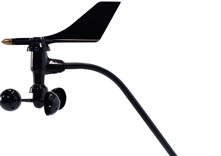
A mechanical wind vane has two design requirements that appear contradictory but work together. First, the weight on either side of the pivot axis must be equal — the vane must be perfectly balanced so it rotates freely without drooping. Second, the surface area on either side must be deliberately unequal — a large, flat tail fin on one end and a narrow pointer (arrowhead, rooster beak, or similar) on the other.
When wind strikes the vane, it pushes against both the tail and the pointer. But the tail — having far more surface area — experiences far greater force. The wind shoves the tail downwind, and the pointer — the path of least resistance — swings to face the source of the wind. The vane continuously readjusts as the wind direction shifts because any change creates a new pressure imbalance on the tail, generating torque around the spindle until the pointer realigns with the incoming flow.
The damping ratio — balancing responsiveness and stability A well-designed professional wind vane must be fast enough to track genuine wind direction changes but not so sensitive that it chases every turbulent fluctuation. In meteorological instrument design, a damping ratio near 0.3 is commonly used as a target because it provides a practical balance between responsiveness and stability. Too little damping and the vane hunts endlessly; too much and it responds sluggishly to real shifts. Precision bearings, optimized tail geometry, and sometimes a small amount of viscous damping in the bearing assembly achieve this balance. |
From Physical Rotation to Digital Signal — How Direction Is Measured
A mechanical wind vane produces continuous physical rotation as a wind direction output — the pointer moves, but there is no electrical signal until a transducer at the base converts rotation angle to a measurable electrical quantity. Three main transducer approaches are used in professional weather instrumentation:
| Transducer Type | How It Works & Operational Trade-offs |
|---|---|
| Potentiometer | A wiper moves along a resistive element as the vane rotates, changing electrical resistance proportional to angle. Simple, inexpensive, and direct. Limitation: the wiper contact wears over time from friction, introducing drift and eventually requiring replacement. A brief “dead zone” occurs where the wiper crosses the ends of the resistive element near 0°/360°. |
| Magnetic encoder (Hall-effect) | A magnet attached to the vane shaft rotates over an array of Hall-effect sensors that detect the magnetic field angle without physical contact. No wear, no dead zone — full 360° of continuous, contact-free measurement. High resolution (sub-degree), high durability, and immune to corrosion and moisture degradation. The standard in professional weather instrumentation for outdoor long-term deployment. |
| Optical encoder | A slotted or patterned disc rotates with the vane past a light source and photodetector. ‘Absolute’ encoders know their exact position at all times — even after a power outage — without needing to home to a reference position. Very high resolution. Used in research-grade instruments. More complex and costly than Hall-effect designs. |
| Ultrasonic (no vane) | Ultrasonic anemometers measure wind direction without any moving parts by comparing the time-of-flight of sound pulses across multiple axes. The direction cyclonePort leads with — see Section 04 for the full comparison. |
04 Sensor Technology — Mechanical Vane vs. Ultrasonic Wind Direction
Wind direction in a cyclonePort station is measured by the same sensor that measures wind speed — either a mechanical cup-and-vane assembly or an ultrasonic anemometer. The technology choice involves real operational trade-offs relevant to the deployment environment.
Mechanical Cup-and-Vane Systems
In a combined cup-and-vane instrument, three rotating cups measure wind speed while a separate vane on the same assembly measures wind direction. The vane uses a magnetic Hall-effect encoder at its base to produce a continuous 0–360° output without a dead zone and without the wear associated with potentiometer contacts.
- Advantages: Lower cost, lower power consumption (passive cup rotation, encoder draws minimal current), suitable for solar-powered remote deployments, proven long-term reliability in mild-to-moderate environments, easy field servicing and calibration.
- Limitations: Moving parts are subject to wear over multi-year deployments. Ice, snow, and freezing rain can temporarily immobilize the vane — blocking rotation until the temperature rises above freezing. In severe icing environments, a heated housing option is available but adds power demand. Higher starting-speed threshold than ultrasonic sensors, meaning very light winds may not consistently register directional data.
Ultrasonic Wind Direction (cyclonePort Primary)
Ultrasonic anemometers measure both wind speed and direction without any moving parts. Pairs of piezoelectric transducers — typically arranged in a triangular or cross-shaped geometry — alternately transmit and receive ultrasonic pulses across the measurement path. When wind blows across the path, it accelerates the pulse traveling with the wind and decelerates the pulse traveling against it. By measuring the time-of-flight difference across multiple axes simultaneously, the instrument resolves the wind vector into both speed and direction components.
- Advantages: No moving parts means no mechanical wear, no ice-induced bearing failures, and no bearing lubrication requirements. Response time under 0.2 seconds allows resolution of rapid directional shifts that a mechanical vane would miss — particularly important for gust front and wind-shift detection. Starting threshold at or near zero — ultrasonic sensors measure direction at wind speeds too low to move a mechanical vane. No dead zone in direction measurement. No regular field maintenance beyond periodic transducer cleaning.
- Limitations: Higher upfront cost than mechanical systems. Requires continuous power — no passive solar-only option for low-power deployments. In heavy rain, water droplets temporarily alter the transit time of ultrasonic pulses, potentially introducing brief direction measurement noise during intense precipitation events.
Windsocks — The Visual Complement to Digital Wind Direction
A windsock, also called a wind cone, is a fabric cone mounted so that its open end faces into the wind. As it inflates, it provides an immediate visual indication of wind direction, and the degree of its extension gives a rough sense of wind speed. Because it is visible from a distance and does not require electrical power or a digital interface, a windsock remains a useful visual wind indicator in aviation and industrial settings.
Its limitation is precision. A windsock provides approximate directional and speed information, but it does not generate timestamped records, digital data, or automated alerts. That makes it valuable for immediate situational awareness, while a digital wind direction sensor supports trend analysis, documentation, remote monitoring, and safety-system integration.
cyclonePort stations complement existing windsocks rather than replace them. The digital wind direction sensor provides the precise, logged data that the windsock cannot — while the windsock remains the immediate visual reference for anyone on the ground or in an aircraft who cannot check a dashboard in real time.
Which Technology for Your Deployment
| Deployment Scenario | Recommended Technology |
|---|---|
| Remote, solar-powered, mild climate | Mechanical cup-and-vane — lower power, adequate performance, easy field service. |
| Moderate climate, cost-sensitive | Mechanical cup-and-vane — proven, reliable, appropriate for most standard weather surveillance applications. |
| Icing environment (mountain, high-latitude) | Ultrasonic with heated transducers — eliminates the icing-induced measurement failure risk of mechanical sensors. |
| Critical gust-front detection (aviation, events) | Ultrasonic — sub-0.2-second response resolves rapid directional changes that mechanical sensors miss. |
| Fire weather, hazmat, smoke plume tracking | Ultrasonic preferred — zero starting threshold and fast response capture the low-speed, rapidly shifting directional data critical for plume dispersion tracking. |
| Standard multi-hazard facility (schools, stadiums, construction) | Either works; cyclonePort configures based on site climate, power availability, and performance requirements. |
05 Vector Averaging — Why Wind Direction Averaging Requires Special Math
Wind direction cannot be averaged using simple arithmetic. The problem is immediately obvious at 0°/360°: a wind that blows from 350° for five minutes and then from 010° for five minutes has an average direction of 360° (north) — but simple arithmetic gives (350 + 10) / 2 = 180° (south), which is exactly wrong. Circular statistics require a different approach.
The correct method treats each wind observation as a vector — decomposing it into northward and eastward components using trigonometry, averaging the components separately, and then computing the resultant direction from the averaged components. This is called vector averaging, and it is the standard specified by the WMO and used in all professional weather data systems including NOAA ASOS.
| Why vector averaging matters operationally |
| A vector-averaged wind direction provides a meaningful summary of the prevailing flow over the averaging period and can be compared consistently across stations. |
| A simple arithmetic average of directions that cross 0°/360° can produce a physically meaningless result. |
| Rapid changes in vector-averaged direction can help identify frontal passages, outflow boundaries, sea-breeze fronts, and other important surface boundaries. |
| Using standard vector-averaging methods and common reporting windows improves comparability with professional meteorological observations. |
| cyclonePort’s RadarOmega platform applies vector averaging to all wind direction data before display and export. |
06 Siting & Mounting — The WMO 10-Meter Standard and Why It Matters
Wind direction readings are highly sensitive to obstructions in the sensor’s upwind exposure. Buildings, trees, terrain features, and even the station mast itself all create turbulence wakes that distort the true wind direction. Accurate, operationally meaningful wind direction data requires clear, representative exposure.
The WMO standard for wind measurement — 10 meters above the surface Standard meteorological wind observations are commonly referenced to a height of 10 meters (33 feet) above ground in open exposure. A widely used siting rule of thumb is to keep major obstacles at least 10 times their height away from the sensor wherever possible. This standard is not arbitrary: 10 meters is the conventional reference height used for many weather observations, model outputs, and forecast products, and it is less affected by immediate near-surface roughness than sensors mounted much lower. Sensors installed well below 10 meters, or close to buildings and other obstructions, may differ significantly from standard regional observations because they are more strongly influenced by local turbulence and flow distortion. cyclonePort advises on siting for each deployment to achieve the best practical exposure available at the site. |
Siting Principles
- Exposure radius: The horizontal distance from the sensor to any obstruction should be at least 10 times the height of the obstruction. A 5-meter tree or wall should be at least 50 meters from the sensor. This is frequently impossible at urban or facility sites — in those cases, document the deviations and their likely effects.
- Upwind priority: The most critical exposure is in the direction of prevailing or operationally significant winds. If the primary purpose is detecting storm approach from the southwest, maximize upwind clearance in the southwest quadrant even if other quadrants have obstructions.
- Away from local heat and exhaust sources: HVAC exhausts, generators, and industrial processes create local convective air movement that distorts both wind speed and direction readings independent of the true ambient wind.
- Mast positioning: On rooftops or elevated structures, the sensor should be mounted well above the roofline — at least 3–4 meters above the roof surface — to clear the recirculation zone created by the building’s upwind face. A sensor in the recirculation zone will read chaotic, non-representative directional data.
- True-north alignment: During installation, the north marker on the wind direction sensor must be aligned with true geographic north — not magnetic north. Use a GPS-based azimuth tool or a known bearing to a landmark for alignment. cyclonePort’s installation process includes this step as standard.
07 Operational Applications
Weather Forecasting — Storm Front and Air Mass Detection
Wind direction shift is one of the most reliable surface observations of a frontal passage. A cold front arriving from the northwest produces a characteristic wind sequence: southeast-to-south winds ahead of the front (warm, humid, unstable air), often with backing or variable direction as the front arrives, followed by an abrupt shift to northwest behind the front (cooler, drier, stable air). This directional signature is detectable at the surface before the rain band, before the lightning, and before any visible sky change.
Fire Weather — Wind Direction as the Critical Fire Spread Variable
Wind direction determines the direction of fire spread, the location of spotting (airborne embers carried beyond the fire perimeter), and the positioning of safe zones and escape routes for firefighting personnel. Fire behavior models treat wind direction as a primary input controlling fire spread direction.
A sudden, unexpected shift in wind direction is one of the most dangerous events in wildland fire operations. Wind shifts can reverse the direction of fire spread in seconds, cutting off personnel who were positioned safely upwind. Real-time wind direction monitoring at fire weather stations provides the situational awareness that allows crews and incident commanders to anticipate and respond to directional changes before they become life-safety events.
- Smoke dispersion planning: Wind direction determines where smoke from prescribed burns, wildfires, and industrial fires will travel. Smoke management regulations for prescribed burning require knowing the transport wind direction at the time of ignition and throughout the burn period. Real-time wind direction data from cyclonePort stations supports compliance with smoke management plans.
Hazmat and Chemical Plume Tracking
When a chemical release, industrial accident, or HVAC refrigerant leak occurs at or near a monitored facility, wind direction is the first operational datum needed: where is the plume going? Which zones should be evacuated immediately and which can shelter in place? Which downwind receptors — residential areas, schools, waterways — are at risk?
cyclonePort’s real-time wind direction data, combined with wind speed, can help determine the current transport direction within seconds of an incident. The RadarOmega platform can display the current wind vector, historical direction data for the past hour, and the directional trend — all of which feed directly into plume dispersion modeling and protective action decisions.
Construction and Crane Operations
Wind direction is operationally critical on construction sites for two distinct reasons: crane safety and airborne hazard management.
Crane operations are particularly sensitive to wind direction because crosswinds — perpendicular to the direction of a lift — create load sway that can cause the load to strike personnel, structures, or the crane itself. Many crane manufacturers specify shutdown thresholds in terms of both speed and direction relative to the lift operation. A cyclonePort station gives the crane operator real-time knowledge of not just how fast the wind is blowing but from which direction — allowing the operator to orient lifts to minimize crosswind exposure and to detect directional shifts that change the crosswind geometry mid-lift.
For airborne hazards — concrete dust, silica, welding fumes, chemical vapors — wind direction determines which workers and which areas of the site are in the downwind exposure zone at any given time. cyclonePort’s directional wind data allows safety managers to dynamically position workers upwind of dust and fume sources and to issue targeted warnings when direction shifts to place previously safe zones into the exposure path.
Aviation and Airport Operations
Wind direction is among the most operationally critical weather variables for aviation. Aircraft must take off and land into the wind whenever possible — a headwind reduces ground speed and decreases required runway length, while a crosswind or tailwind creates safety risk. Runway selection at multi-runway airports is driven by wind direction. For single-runway airports and helipads, real-time wind direction determines whether operations are within aircraft crosswind limitations.
For private airfields, heliports, agricultural aviation operations, and UAS (drone) operations near cyclonePort-monitored facilities, continuous wind direction monitoring through RadarOmega provides the real-time data needed for safe go/no-go decisions and operational planning around wind windows.
Agriculture — Spray Drift Control and Frost Management
Wind direction is among the most consequential variables in agricultural operations — both for pesticide application compliance and for frost protection.
- Spray drift control: Pesticide and herbicide application regulations in most states prohibit spraying when wind direction would carry drift onto neighboring crops, sensitive habitats, water bodies, or residential areas. Real-time wind direction from a cyclonePort station gives applicators the objective, logged data needed to confirm that application was conducted under compliant directional conditions — and to stop operations when wind direction shifts the drift zone toward a protected receptor.
- Frost protection scheduling: Katabatic (downslope) cold air drainage flows are a significant frost risk in many agricultural areas, particularly orchards and vineyards in hilly terrain. These flows follow topography-driven wind patterns that differ from regional forecast winds. On-site wind direction monitoring allows growers to detect when cold drainage is occurring and initiate frost protection measures — heating, irrigation, or fan mixing — before temperatures drop to damaging levels.
- Irrigation scheduling: Wind direction influences irrigation efficiency and drift. Sprinkler systems operating when wind is blowing toward buildings, roads, or downslope areas waste water and create hazards. Wind direction data allows automated irrigation controllers to pause or redirect systems based on current directional conditions.
Ports, Marinas, and Marine Operations
Shifting offshore winds create docking hazards that are difficult to anticipate from a vessel approaching a slip or pier. Wind direction from a mast-mounted sensor on the dock provides the berth manager and approaching captain with real-time knowledge of the wind angle relative to the dock face — the key variable for predicting whether a vessel will be pushed into or away from the dock during approach. This information, available via RadarOmega from a cyclonePort unit on any mobile device, allows marine operators to plan approach angles, call for assistance, or delay docking until conditions improve.
For commercial fishing operations, ferry terminals, and maritime emergency response, wind direction also determines sea state development and safe exit/entry routing from harbors and inlets. Wind data from on-site cyclonePort stations provides site-specific directional information that regional offshore forecasts cannot match.
Emergency Management and Environmental Monitoring
Emergency managers use wind direction data to make shelter-in-place vs. evacuation decisions, route evacuations around downwind hazard zones, and position emergency resources upwind of incident scenes. For nuclear, chemical, and radiological incidents, the first operational question after confirmation of a release is always: what direction is the wind blowing, and what is downwind?
Environmental monitoring programs — air quality networks, industrial facility fence-line monitoring, agriculture irrigation scheduling — all incorporate wind direction data to correlate measured pollutant concentrations with their upwind sources, to schedule operations around favorable wind patterns, and to document compliance with air quality regulations.
08 Instrument Selection Guide — What Separates Professional Wind Direction Systems
Wind direction sensors span a wide range of performance, durability, and data quality. These criteria distinguish professional weather surveillance instrumentation from consumer-grade devices.
| Specification | What to Require |
|---|---|
| Measurement Range | 0–360° full circle with no dead zone. Many low-cost potentiometer-based sensors have a dead zone of 2–15° near the 0°/360° transition, where direction output is unreliable. Professional sensors using Hall-effect magnetic encoders or ultrasonic measurement have no dead zone. |
| Accuracy | Professional standard: ±2–3° under steady-state conditions. Consumer sensors: ±5–20°. At 20° accuracy, a sensor cannot distinguish between a northwest and a north-northwest wind — a difference that matters significantly for frontal passage detection, fire weather, and chemical plume tracking. |
| Resolution | 1° resolution is the professional standard, providing the directional precision needed for NWS-comparable data. 16-point compass (22.5° resolution) or 8-point cardinal-only outputs are inadequate for professional applications. |
| Transducer Type | Hall-effect magnetic encoder: no contact wear, no dead zone, suitable for long-term outdoor deployment. Preferred over potentiometer designs for durability. Ultrasonic: no moving parts, fastest response, best icing performance. Potentiometer: acceptable for short-term or low-duty deployments only. |
| Vector Averaging | The platform must compute and report vector-averaged wind direction — not simple arithmetic averages. Confirm this explicitly. This is the standard for all WMO-compliant and NWS-comparable observations. |
| Starting Threshold | Ultrasonic: effectively zero. Hall-effect vane: typically 0.5–1 m/s. Consumer vanes: can require 1–3 m/s before registering direction. For applications requiring direction data in light-wind situations — fire weather, chemical dispersion, airport taxiway wind monitoring — low starting threshold matters. |
| True-North Alignment | The sensor must support alignment to true geographic north — not just be able to point in any direction. Systems should document the alignment process and provide a means to verify it. RadarOmega displays all direction data referenced to true north. |
| Update Rate | 1-second or faster updates for gust-front and rapid wind-shift detection. 10-minute averages per WMO for standard meteorological reporting. Both should be available simultaneously. |
| Icing Performance | Mechanical vanes can be frozen temporarily by ice accumulation on the vane fin or shaft. Heated vane options reduce this risk. Ultrasonic sensors with transducer heating eliminate it entirely. Verify the icing performance specification for the climate of the deployment site. |
| Integration | Wind direction data is most valuable in context: alongside wind speed and gusts, barometric pressure trend, temperature, humidity, lightning, and rain from the same station. Standalone wind direction devices without multi-sensor integration provide limited operational value for the applications described in this page. |
09 Installation & Maintenance
Installation
- True-north alignment is the most critical installation step for wind direction sensors. Errors in alignment directly produce systematic directional errors across all subsequent readings. Use a GPS-based azimuth tool or a precise compass declination-corrected bearing to align the sensor’s north reference to true geographic north. Verify the alignment by checking the sensor output against known wind direction from a nearby official ASOS or AWOS station during a period of steady wind.
- Mount height: 10 meters (33 feet) is the WMO standard. Where this is not achievable at a facility site, document the mounting height and the obstruction characteristics of the surrounding environment so that users understand the limitations of the data.
- Surge protection: Route cables through proper surge protection (rated to 20 kA or higher for lightning-prone locations). Wind direction sensors are typically mounted at height on masts — attractive targets for induced surge voltage during nearby lightning.
- Level mounting: The wind vane spindle must be vertically plumb. A tilted spindle introduces a systematic directional bias because the weight distribution of the vane assembly — which is balanced for vertical mounting — becomes unequal when tilted, causing the vane to favor one direction.
Maintenance — Mechanical Vane
- Bearing inspection: Annually inspect the vane bearings for wear, corrosion, or contamination. Stiff or gritty bearings increase starting threshold and introduce hysteresis (the sensor may read different directions for the same wind depending on which direction it most recently came from). Replace bearings at first signs of resistance.
- Vane fin condition: Inspect the tail fin for physical damage — cracks, missing material, or deformation — that would change its aerodynamic profile and directional responsiveness. Even modest damage to the fin can introduce directional bias.
- Encoder verification: Verify the Hall-effect encoder output periodically by manually rotating the vane and confirming the direction output tracks the physical position throughout the full 360° range.
- True-north alignment check: Re-verify alignment annually, particularly after any maintenance that required removal and reinstallation of the sensor assembly.
- Stuck-sensor detection: RadarOmega flags suspicious data patterns — including stuck readings that show less than 1° variance over several consecutive minutes when wind speeds are above the starting threshold. This automated diagnostic prompts inspection before the sensor failure becomes invisible in the data stream. Review platform health status alerts regularly.
Recommended inspection frequency by environment:
| Environment | Inspection Frequency |
|---|---|
| School / office / benign environment | Quarterly visual inspection and spin test. |
| Coastal or desert environment | Monthly — salt spray and sand accelerate bearing and finish degradation. |
| Industrial site with airborne pollutants | Monthly or more frequent — particulates, chemical vapors, and corrosive atmospheres accelerate wear on bearings and encoder components. |
| Post-severe-weather event | Inspect after any event with sustained winds above 60 mph or hail — physical damage can be subtle and directional bias can develop without obvious failure. |
Maintenance — Ultrasonic Sensor
- Transducer cleaning: Periodically clean the ultrasonic transducer faces with a soft, lint-free cloth to remove dust, pollen, spider webs, and debris that can attenuate the acoustic signal and introduce measurement error.
- Obstruction check: Inspect for anything resting on or bridging between the transducer arms — insects, nesting material, ice — that could block or alter the acoustic path.
- Signal diagnostics: RadarOmega includes sensor health monitoring that flags anomalous direction readings. Review health status logs periodically to catch early signs of transducer degradation.
10 cyclonePort Wind Direction System — Platform, Integration & Deployment
cyclonePort weather surveillance stations include a wind direction sensor as a core component of every standard configuration, delivering continuous 0–360° directional data through the RadarOmega platform alongside all other station sensor streams.
Technical Specifications
| Parameter | Specification |
|---|---|
| Measurement Range | 0–360°, no dead zone — full circle continuous measurement |
| Accuracy | ±2–3° under steady-state conditions (Hall-effect vane or ultrasonic) |
| Resolution | 1° |
| Sensor Options | Hall-effect magnetic encoder wind vane (standard); ultrasonic (recommended for icing environments and gust-front detection) |
| Starting Threshold | 0.5–1 m/s (mechanical vane); effectively 0 m/s (ultrasonic) |
| Response Time | <0.2 seconds (ultrasonic); aerodynamic response distance applies to vane designs |
| Averaging Method | Vector-averaged direction — WMO-standard sinusoidal decomposition; 2-minute and 10-minute averages available |
| Reporting Intervals | Instantaneous, 2-minute, and 10-minute vector-averaged direction; configurable summary intervals |
| True-North Reference | Aligned to true geographic north during installation; GPS-based azimuth verification provided |
| Direction Output | Degrees clockwise from true north; compass sector labels available |
| Operating Temperature | –40°C to +60°C standard; heated vane/transducer option for icing environments |
| Environmental Rating | IP65+; integrated into cyclonePort station housing |
| Connectivity | RS-485/Modbus; cellular, Wi-Fi, or Ethernet transmission |
| Data Access | Web portal, mobile app, REST API via RadarOmega |
| Data Export | CSV and JSON with timestamps; SCADA integration available |
| Station Lifespan | 10+ years with standard maintenance |
Specifications may vary by model. Contact cyclonePort for current engineering documentation.
What the System Delivers
- Continuous real-time wind direction — 0–360° vector-averaged bearing updated every second, displayed alongside wind speed and gusts in RadarOmega
- Historical direction archive — directional history for every station
- True-north referenced data — all direction data referenced to true geographic north for direct comparability with regional weather observations
- Multi-station wind map — view wind direction arrows for all stations simultaneously in RadarOmega to track front passage, sea breeze fronts, and outflow boundaries across a monitored region
- Full weather picture — direction alongside speed, gusts, temperature, humidity, pressure, rain, lightning, and camera from the same station
Who Deploys cyclonePort Wind Direction Monitoring
| Sector | What cyclonePort Enables |
|---|---|
| Emergency Management | Real-time wind direction for shelter-in-place and evacuation decision support. Chemical and smoke plume tracking. Multi-station wind maps for regional situational awareness during severe weather and hazmat events. |
| Fire Weather & Land Management | Wind direction monitoring at fire weather stations and prescribed burn sites. Real-time direction for fire spread prediction, smoke management, and crew safety positioning. Wind-shift alerts for sudden direction changes. |
| Outdoor Athletic Programs | Wind direction context alongside WBGT and lightning data. |
| Construction & Industrial | Crane crosswind monitoring. Airborne hazard dispersion tracking. On-site wind monitoring for elevated and outdoor work operations. |
| Aviation & Heliports | Continuous runway wind direction for crosswind calculations. Wind-shift detection for IFR/VFR go/no-go decisions at private airfields and rooftop helipads. |
| Environmental & Research | Long-term directional frequency data. Air quality source attribution via directional correlation with measured pollutants. Microclimate characterization for complex terrain. |
Deploy Wind Direction Monitoring at Your Facility cyclonePort wind direction sensors are available as part of complete weather surveillance stations. Contact our team to configure sensor technology, mounting specifications, and true-north alignment for your specific application. info@cycloneport.com · 844-737-9328 · cycloneport.com/contact |
11 Frequently Asked Questions
What is a wind vane and what does it measure?
A wind vane measures the direction from which the wind is blowing. Wind direction is reported in degrees from true north and provides important information about air-mass source, weather changes, and transport direction for smoke or airborne hazards.
What is the difference between a wind vane and an anemometer?
A wind vane measures wind direction, while an anemometer measures wind speed. Many weather stations combine both functions in one wind instrument.
What does wind direction tell you about weather?
Wind direction often gives useful clues about the air mass and weather pattern affecting a location, though the meaning depends on region, season, and terrain. Sustained wind shifts can signal fronts or other important boundaries.
Why is wind direction reported as where it comes from rather than where it goes?
Because the source region of the air often helps describe its characteristics, and that convention matches how a wind vane physically points into the wind.
What is wind direction shift and why does it matter operationally?
A wind shift is a noticeable change in wind direction. It matters because it can change runway use, smoke dispersion, fire behavior, and hazard zones, and it may indicate the passage of a front or other boundary.
What does vector averaging mean for wind direction?
Vector averaging treats wind observations as directional vectors rather than averaging angles directly, which avoids errors near the 0°/360° boundary and provides a meaningful mean direction.
What is the WMO standard for wind sensor mounting height?
Standard meteorological wind observations are commonly referenced to 10 meters above ground in open exposure. Lower or obstructed siting can distort wind measurements.
Can a cyclonePort wind direction sensor be used for fire weather monitoring?
Yes. Wind direction is an important part of fire-weather monitoring and, when combined with other observations, can support smoke management, fire behavior awareness, and crew safety decisions.
Related Instruments & Guides
Wind direction is one component of the complete cyclonePort weather station. Explore related instrument pages:
↗ Wind Meter & Anemometer — Wind speed, gust measurement, and Beaufort/Saffir-Simpson context
↗ Barometric Pressure Sensor — Pressure trend analysis for front detection alongside directional wind data
↗ Lightning Detection System — Lightning detection integrated with wind direction for complete storm awareness
↗ WBGT Monitor & Heat Stress Sensor — Heat stress monitoring with wind direction context for heat index and comfort
↗ Temperature Sensor — Air temperature monitoring alongside wind chill and heat index calculation
↗ Humidity Sensor & Hygrometer — Relative humidity and dew point with wind direction for air mass characterization
↗ Rain Gauge — Precipitation monitoring alongside wind direction for storm tracking and front passage documentation






Built for Severe Weather
Remote system management from anywhere
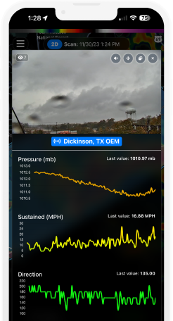
Deploy high-quality PTZ (Pan-Tilt-Zoom) IP cameras designed for effortless setup and immediate operation through plug-and-play simplicity. This advanced design significantly reduces installation time and complexity, making sophisticated surveillance accessible for businesses of all sizes. Multiple cameras connect seamlessly to the network.
Remote system management from anywhere
Deploy high-quality PTZ (Pan-Tilt-Zoom) IP cameras designed for effortless setup and immediate operation through plug-and-play simplicity. This advanced design significantly reduces installation time and complexity, making sophisticated surveillance accessible for businesses of all sizes. Multiple cameras connect seamlessly to the network.
Remote system management from anywhere
Deploy high-quality PTZ (Pan-Tilt-Zoom) IP cameras designed for effortless setup and immediate operation through plug-and-play simplicity. This advanced design significantly reduces installation time and complexity, making sophisticated surveillance accessible for businesses of all sizes. Multiple cameras connect seamlessly to the network.
Remote system management from anywhere
Deploy high-quality PTZ (Pan-Tilt-Zoom) IP cameras designed for effortless setup and immediate operation through plug-and-play simplicity. This advanced design significantly reduces installation time and complexity, making sophisticated surveillance accessible for businesses of all sizes. Multiple cameras connect seamlessly to the network.
Learn From The Field

- Guides
Cal/OSHA Heat Regulations for Outdoor Workers: What California Employers Must Know
- Guides
GCSAA Lightning Safety Guidance for Golf Courses: A Complete Compliance Guide