Wind Meter & Anemometer
Professional wind speed and direction measurement for weather surveillance networks — delivering real-time sustained speed, gust, and directional data to emergency managers, broadcast meteorologists, utility operators, construction safety teams, and critical infrastructure professionals.
Contents
01 The Instrument — What a Wind Meter Measures and Why It Matters
02 How the cyclonePort Anemometer Works
03 Anemometer Types & Technology Comparison — Cup vs. Ultrasonic
04 Wind Speed Scales & Operational Thresholds
05 Operational Applications — What Wind Data Enables
06 Instrument Selection Guide — Specs That Matter in the Field
07 Installation & Maintenance
08 cyclonePort Wind Monitoring System — Platform, Integration & Deployment
09 Frequently Asked Questions


- 0–200+ mph
- 0.3 mph / ±3°
- Speed · Gust · Direction
- RadarOmega
01 The Instrument — What a Wind Meter Measures and Why It Matters
A wind meter — more precisely called an anemometer — is a meteorological instrument that measures wind speed and, in most professional deployments, wind direction simultaneously. It is one of the oldest and most operationally critical instruments in atmospheric science, and one of the first sensors that organizations deploying professional weather surveillance networks must get right.
In the cyclonePort weather monitoring system, the anemometer is a standard module in every station, operating in continuous real-time alongside temperature, humidity, rain gauge, and barometric pressure sensors. Wind data feeds directly into the RadarOmega platform, where sustained speed, wind gust, and wind direction are logged and visualized.
Wind speed and gust — a critical distinction Sustained wind speed is the average wind velocity over a defined period. Wind gust is the peak instantaneous wind speed recorded within that same period. cyclonePort instruments capture both. |
Wind is not simply a comfort variable. It is a primary driver of wildfire spread, structural loading, crane safety decisions, outdoor event cancellations, utility infrastructure stress, and severe weather classification. Without accurate, real-time, site-specific wind data, operations teams are making consequential safety and liability decisions based on airPort observations that may be miles away and hundreds of feet lower than their actual site conditions.
02 How the cyclonePort Anemometer Works
cyclonePort weather stations use an ultrasonic anemometer as the primary wind sensing technology — eliminating moving parts, removing mechanical wear as a failure mode, and delivering faster gust response than cup-and-vane designs. Cup-and-vane configurations are also supPorted for deployments where power budget or cost is the governing constraint.
Ultrasonic Sensing — The cyclonePort Primary Technology
Ultrasonic anemometers measure wind speed and direction using pairs of piezoelectric transducers that emit high-frequency sound pulses across fixed paths. Wind blowing with a pulse shortens its travel time; wind opposing it lengthens it. By measuring transit time in both directions across multiple transducer pairs, the sensor simultaneously calculates wind speed and direction — with no moving parts involved.
- Pulses are emitted continuously at 10 Hz or faster, resolving gusts and rapid directional shifts in near-real time with a response time under 0.2 seconds
- Speed resolution of 0.01 m/s and a starting threshold as low as 0.1 m/s — capturing light air conditions that cup designs cannot detect
- Full 0–360° direction coverage with no dead zones — no vane orientation or dead-spot management required
- All values are timestamped and transmitted continuously to RadarOmega
Cup-and-Vane — SupPorted Alternative Configuration
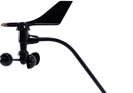
The cup anemometer measures wind speed through rotation of three hemispherical cups on a vertical axis. A separate wind vane measures direction via potentiometer or contactless encoder. Cup-and-vane systems draw microamp-range passive power — making them the right choice for solar-powered remote deployments where power budget is the primary constraint.
- Reed-switch or encoder pulse output per rotation — each pulse represents a known increment of wind speed
- Mechanical starting threshold ~0.5–1.0 mph; aerodynamic response lag means rapid gusts may not be fully captured during rotor acceleration
- Vane potentiometer designs have a 2–5° dead spot — orient away from prevailing wind direction at installation; contactless encoder vanes eliminate this
Icing risk with cup-and-vane Icing failures affect cup anemometers in approximately 20–30% of winter operations in cold climates — freezing rain and rime ice can stall rotation entirely, producing zero readings during active weather events. Ultrasonic sensors reduce this risk through path geometry that resists ice accretion. For extreme environments, electrically heated housings (20–50W pulsed) are available to keep both cup/vane mechanisms and ultrasonic transducer paths clear. |
What the Anemometer RePorts
- Sustained wind speed (mph, km/h, knots, or m/s) — rolling average over a user-configurable period, typically 2 minutes
- Wind gust (peak instantaneous speed) — highest recorded value within the reporting interval
- Wind direction (0–360°) — compass bearing from which wind is blowing, updated continuously
- Wind run (optional) — cumulative distance of air movement over a period, used in evapotranspiration and agricultural calculations
- Historical archive — all data logged with timestamps in RadarOmega for trend analysis, after-action review, and event documentation
03 Anemometer Types & Technology Comparison — Cup vs. Ultrasonic
Two technologies dominate professional weather station anemometry: rotating cup-and-vane and ultrasonic. Understanding the genuine trade-offs — rather than marketing claims — is what guides the right selection for a given deployment.
| Type | Characteristics |
|---|---|
| Ultrasonic (Sonic) — cyclonePort Primary | Measures wind speed and direction with no moving parts by timing ultrasonic sound pulses between paired transducers. No startup threshold — responds to winds as low as 0.1 m/s. Response time under 0.2 seconds captures rapid gust events. Sampling rates above 10 Hz enable 0.01 m/s resolution. Full 360° direction coverage with no dead zones. |
| Strengths | No moving parts — zero bearing wear · No starting threshold · Gust response under 0.2 seconds · Single unit measures speed and direction · No dead zone in direction measurement · Resilient to most icing conditions · IP66+ rated |
| Limitations | Higher cost than cup designs · Higher power draw (30–60 mA active vs. microamp passive for cup) · Heavy rain can briefly affect signal quality · Temperature affects speed of sound (onboard compensation required) · Transducer faces sensitive to insect/bird contamination |
| Cup & Vane (Mechanical) — SupPorted Alternative | Three rotating cups measure wind speed; a separate vane measures direction. Reed-switch output is essentially passive — microamp-range power draw makes cup-and-vane the preferred choice for solar-powered remote deployments where power budget is constrained. Long operational record and wide speed range up to 200+ mph. Icing failures affect cup mechanisms in ~20–30% of winter operations in cold climates. |
| Strengths | Extremely low power draw · Wide speed range including extreme events · Proven multi-decade operational record · User-serviceable bearings · Solar-compatible without power budget concern · Lower cost |
| Limitations | Mechanical starting threshold (~0.5–1.0 mph) · Moving parts require periodic bearing inspection · Slower gust response due to rotor inertia · Icing can halt rotation · Separate vane required for direction · Vane dead spot in potentiometer designs |
| Propeller / Vane | A propeller anemometer uses horizontally mounted blades that rotate around a horizontal axis, with a tail vane keeping the propeller aimed into the wind. Measures wind speed along a single axis. Less common in general weather station applications; more often found in research or directional monitoring setups. |
| Strengths | Good sensitivity at low to moderate speeds · Directional by design · Some models offer high accuracy |
| Limitations | Prone to icing on blades and vane without heating · Directional measurement requires precise alignment · Less robust in extreme wind events than cup designs |
| Handheld / Portable | Battery-powered handheld devices for spot wind measurements. Suitable for field surveys, personal safety checks, and temporary monitoring. Not appropriate for continuous unattended monitoring, threshold alerting, data logging, or network integration. Used to supplement, not replace, fixed station anemometers. |
| Strengths | Portable · No installation required · Low cost for basic spot checks |
| Limitations | No continuous monitoring · No data logging or alerts · No network integration · Battery-dependent · Not equivalent to fixed station measurement for safety documentation |
04 Wind Speed Scales & Operational Thresholds
Wind speed data has no operational value without context. The scales and thresholds below translate measured wind speed into the decision frameworks that emergency managers, construction safety officers, athletic directors, and utility operators actually use.
The Beaufort Scale — Observational Wind Classification
The Beaufort scale, developed in the early 19th century, classifies wind speed on a 0–12 scale based on observable effects on land and water. It remains a useful reference for communicating wind intensity in practical terms.
| Beaufort Force | Wind Speed & Operational Significance |
|---|---|
| Beaufort 0–1 | Calm to light air: 0–3 mph. Smoke rises vertically. No operational impact for most activities. |
| Beaufort 3–4 | Gentle to moderate breeze: 8–18 mph. Leaves and small branches move. Flags extend. Minimal operational impact; monitor for trend. |
| Beaufort 5–6 | Fresh to strong breeze: 19–31 mph. Small trees sway; moderate waves. Elevated caution for crane operations and outdoor events. Wind loading begins to affect open structures. |
| Beaufort 7–8 | Near gale to gale: 32–46 mph. Whole trees in motion; difficult to walk against wind. Most crane operations should cease. Outdoor event suspension warranted. Utility crews on elevated structures should stand down. |
| Beaufort 9–10 | Strong gale to storm: 47–63 mph. Branches break; minor structural damage. Emergency preparedness activates. All outdoor elevated operations cease. |
| Beaufort 11–12 | Violent storm to hurricane force: 64+ mph. Widespread structural damage; trees uprooted. Full emergency operations mode. |
Operational Wind Thresholds by Sector
The thresholds below are representative of widely-used industry and regulatory guidelines. Site-specific conditions, load type, equipment rating, and applicable regulations always govern final decisions.
| Sector | Operational Wind Threshold |
|---|---|
| Crane Operations | Extreme caution: 0–20 mph. Capacity deductions required: 20–39 mph depending on crane model and boom length. Full shutdown and boom lowered: 40+ mph. Individual lift plans may specify lower thresholds depending on load surface area and configuration. On-site anemometer data — not a forecast — is the required basis for these decisions. |
| Outdoor Athletics (NFHS / State Guidelines) | Lightning policy triggers are the primary threshold for most programs, but sustained winds above 40 mph warrant activity suspension for safety. Extreme heat combined with elevated wind affects WBGT calculations — cyclonePort stations provide both simultaneously. |
| Fire Weather (NWS Red Flag) | RH below 15–25% combined with sustained winds 15–25 mph or higher trigger Red Flag Warning conditions in most fire-prone regions. An on-site anemometer network provides the real-time wind data needed to confirm Red Flag conditions at a specific location rather than relying on regional station interpolations. |
| Utility / Power Operations | Most utilities have internal protocols for suspending aerial linework above 25–30 mph sustained; gusts above 35–40 mph. Wind-driven vegetation contact with lines is a primary cause of outages — sustained wind monitoring along transmission corridors informs vegetation management timing and storm restoration crew staging. |
| Aviation (General) | FAA regulations and aircraft performance data define specific crosswind limits by aircraft type. Weather stations at or near airfields provide the real-time wind data required for takeoff and landing assessments. |
| Scaffolding / Elevated Work | OSHA and most contractor safety programs require suspension of work on scaffolding above 25–30 mph. Site-specific gusts — not regional averages — are the governing metric, making on-site measurement essential. |
Hurricane Wind Classification — Saffir-Simpson Scale
The Saffir-Simpson Hurricane Wind Scale classifies tropical cyclone intensity by maximum sustained wind speed. cyclonePort stations deployed in coastal and southeastern U.S. markets provide ground-level wind observations that complement NWS forecast products during tropical cyclone events.
| Category | Wind Speed & Impact |
|---|---|
| Category 1 | 74–95 mph sustained. Very dangerous winds. Potential for some damage to well-constructed frame homes; power outages expected. |
| Category 2 | 96–110 mph sustained. Extremely dangerous winds. Major roof and siding damage; near-total power loss likely. |
| Category 3 (Major) | 111–129 mph sustained. Devastating damage. Significant structural damage to well-built homes; power outages lasting days to weeks. |
| Category 4 (Major) | 130–156 mph sustained. Catastrophic damage. Most trees snapped; residential structures severely damaged or destroyed. |
| Category 5 (Major) | 157+ mph sustained. Catastrophic damage. Complete roof failure and wall collapse for most structures. |
05 Operational Applications — What Wind Data Enables
Emergency Management — Situational Awareness and Coordination
Wind speed and direction are foundational inputs for emergency management decision-making across the full event lifecycle: pre-event staging, real-time response, and post-event assessment. During severe weather events, the difference between a regional observation and an on-site measurement can span tens of miles and hundreds of feet of elevation — representing fundamentally different conditions.
cyclonePort networks provide emergency managers with real-time wind observations from multiple locations simultaneously. Wind direction data helps track storm motion, plume paths, and post-event debris field assessments.
Wind direction data has a specific and critical role in hazmat and industrial incident response: city emergency managers and industrial safety teams use real-time wind direction to understand smoke, dust, and chemical plume travel during active incidents — determining evacuation zones, shelter-in-place boundaries, and resource staging areas based on where the wind is actually carrying material, not where a regional forecast suggests it should be going.
Broadcast Media and Weather Operations
Broadcast meteorologists need hyperlocal, real-time wind data to accurately characterize severe weather events on-air. A cyclonePort network across a media coverage area allows meteorologists to display live wind observations from dozens of specific locations during storm events: the peak gust at a specific highway interchange, the onset of tropical storm-force winds at a coastal community, the wind shift marking a cold front’s passage.
Wind data in combination with rainfall, temperature, and humidity from the same station gives broadcast operations the complete, live meteorological picture that drives audience trust and advertiser value.
Utilities and Power Infrastructure
Electric utilities face wind-driven risks across thousands of miles of transmission and distribution infrastructure. High winds drive vegetation into lines — the primary cause of outages and wildfires in many regions. Elevated wind speeds combined with low humidity define fire weather conditions that determine when utilities must implement Public Safety Power Shutoffs (PSPS) in fire-prone areas.
cyclonePort stations deployed along transmission corridors provide continuous wind monitoring that helps inform vegetation management scheduling, pre-storm crew staging, line patrol priorities, and PSPS decision thresholds. Wind direction from a distributed sensor network can also help characterize plume paths for outage cause analysis following weather-driven events.
Construction Safety — Crane, Elevated Work & Port Operations
Wind speed is the most operationally consequential weather variable on active construction sites with tower cranes, mobile cranes, and elevated scaffolding. Crane manufacturers specify maximum wind speeds for operation — typically triggering caution protocols at 20 mph and mandatory shutdown at 40 mph for most configurations — but site-specific conditions can differ dramatically from regional forecast values, particularly in urban canyon effects and at elevation.
An on-site cyclonePort anemometer provides the legally defensible, real-time wind data that crane operators, lift supervisors, and site safety officers need to document weather conditions at the time of lift operations. A forecast or nearby airport reading is not a substitute for on-site measurement when lives and equipment are at stake.
Port and maritime operations face the same wind-driven decisions at the waterfront. Docking decisions for large vessels and ship-to-shore crane operations typically halt above 10 m/s (approximately 22 mph) — thresholds where wind loading on tall cranes and vessel surfaces creates control and stability risks. On-site wind monitoring at Port facilities provides the real-time gust and direction data that dock masters and crane operators need, particularly in locations where waterfront exposure produces wind conditions dramatically different from nearby inland stations.
Schools, Athletics, and Large Venue Operations
School districts, athletic programs, and venue operators use wind data in combination with lightning detection and precipitation measurements to make event suspension and resumption decisions. Strong wind thresholds for outdoor athletics, festivals, and venue operations are often embedded in facility safety policies — but those policies require on-site monitoring to be actionable. A cyclonePort station at the venue delivers the real-time wind speed and gust data that transforms a policy from aspirational to operational.
Fire Weather Monitoring
Wind speed, direction, and humidity together define fire weather conditions. cyclonePort stations deployed in fire-prone areas or across utility service territories provide the real-time wind monitoring needed to identify Red Flag conditions at specific locations — not interpolated from distant regional stations. Wind direction data from a distributed network helps model fire spread potential and plume behavior in pre-event planning.
06 Instrument Selection Guide — Specs That Matter in the Field
These are the specifications and design characteristics that separate professional weather surveillance anemometers from consumer or prosumer wind meters — and the considerations that determine whether a cup or ultrasonic configuration is the right choice for a given deployment.
| Specification | What to Require |
|---|---|
| Speed Range | Professional weather surveillance requires a sensor capable of measuring the range of weather-relevant wind speeds — from near-calm conditions to extreme event winds. Instruments rated to 200+ mph are appropriate for deployments in hurricane-prone regions. Instruments with upper limits below 100 mph are not suitable for severe weather monitoring. |
| Speed Accuracy | ±0.3 mph or better at moderate speeds is the specification for professional-grade cup anemometers. Verify accuracy is stated across the relevant operational speed range, not just at a single calibration point. Ultrasonic sensors typically specify ±0.1–0.3 m/s. |
| Direction Accuracy | ±3° or better for professional vane sensors. Potentiometer-based vanes have a 2–5° dead spot — factor this into orientation decisions at installation. Contactless encoder designs eliminate the dead spot. |
| Starting Threshold | The minimum wind speed at which the sensor begins measuring. Cup anemometers: typically 0.5–1.0 mph. Ultrasonic: effectively zero. For most operational applications above 5 mph, starting threshold is irrelevant. For applications involving low-speed urban wind studies or calibration-sensitive research, ultrasonic is preferred. |
| Gust Response | Cup anemometers have an aerodynamic response distance — the distance wind must travel past the sensor before the instrument registers a step change. This introduces a slight lag in gust capture relative to ultrasonic sensors, which respond instantaneously. For most safety threshold applications this is not operationally significant. For high-frequency gust research or aviation applications, ultrasonic is preferred. |
| Power Consumption | Cup anemometers with reed-switch output draw microamp-range power — essentially passive. Ultrasonic sensors require 30–60 mA active power continuously. In solar-powered remote deployments, this difference can be significant to battery and panel sizing. |
| Environmental Rating | Outdoor sensors must withstand UV exposure, precipitation, temperature extremes (–40°C to +60°C for most professional sensors), insects, and physical impact. Verify IP65 or higher rating. For coastal or corrosive environments, stainless steel hardware and marine-grade coatings are essential. |
| Bearing & Wear | Cup anemometers have bearings that wear over years of continuous operation. Professional-grade sensors use precision sealed bearings rated for 5+ year service life. Verify bearing replacement is user-accessible for field service. |
| Network Integration | A standalone wind meter displays a number. A networked anemometer delivers data — historically archived, alert-enabled, API-accessible, and visible alongside all other sensor streams from the same station. Verify platform integration and telemetry options before hardware selection. |
| Heated Option | For deployments in climates where ice formation during precipitation events is a risk, heated cup/vane assemblies prevent measurement gaps caused by frozen moving parts. Essential for year-round monitoring at high-elevation or northern-latitude sites. |
07 Installation & Maintenance
Anemometer siting is the single factor with the greatest impact on measurement quality. An instrument-grade sensor in a poorly chosen location will consistently produce data that misrepresents actual ambient wind conditions — sometimes by a factor of two or more in complex terrain or urban environments.
Siting Best Practices
- Standard mounting height: WMO recommends 10 meters (33 feet) above ground for standard meteorological wind observations — the reference height for most wind speed norms, safety standards, and forecast models. For practical site deployments, 6–10 meters is the target range. Measurements at non-standard heights should be noted in data documentation.
- Obstruction clearance: Obstructions — buildings, trees, towers — significantly distort airflow and produce unrepresentative readings. The anemometer should be mounted at a height at least 1.5–2× the height of the tallest nearby obstruction within a 10× height radius. In practice: keep the sensor as high and as exposed as the site permits.
- Avoid building wake zones: Mounting an anemometer on the downwind side of a building creates a turbulent wake that dramatically underestimates open-terrain wind speeds. Mount on the windward face or above the roofline if rooftop installation is unavoidable — and note that buildings accelerate flow over rooftops by 20–50%, meaning rooftop-mounted sensors may systematically over-rePort ambient wind speeds even when they are clear of the immediate wake zone.
- Avoid funneling and channeling: Streets, valleys, and gaps between structures can accelerate or redirect wind, producing readings that are not representative of broader conditions. Be aware of prevailing wind direction at the site and avoid locations where terrain creates artificial channeling.
- North orientation of vane: Wind vanes should be oriented with the reference mark pointing true north, established with a compass during installation. Incorrect north orientation produces systematically offset direction readings.
- Separation from other sensors: Maintain adequate separation from temperature radiation shields, rain gauge funnels, and camera housings — airflow disturbance from adjacent hardware affects wind readings at close range.
Urban deployments, microclimates, and surge protection Urban environments present the most challenging anemometry conditions. Building wakes, street canyon channeling, and rooftop updrafts can produce wind data that is locally accurate but not representative of conditions at human height. Real-world example: a coastal facility may record 15 m/s at a pier while an adjacent warehouse reads only 8 m/s due to channeling effects — both readings are correct for their exact location, but only one may be representative of site-wide conditions. For complex layouts, cyclonePort supPorts multiple wind sensors to capture spatial variation. Additionally: in lightning-prone deployments, cable routing should include surge protection rated above 20 kA to protect data logger electronics from transient events. |
Calibration
cyclonePort anemometers are factory-calibrated to verify the relationship between rotation rate (or transit time for ultrasonic) and wind speed before shipping. Cup anemometer calibration is mechanically defined by cup geometry and arm length — it is stable over time and does not drift the way humidity or temperature sensors do.
Field verification can be performed by comparing readings with a co-located reference instrument or with nearby official NWS ASOS observations during periods of steady, uniform wind. For research or regulatory applications requiring the highest accuracy, laboratory wind-tunnel calibration verification is available from the sensor manufacturer.
Routine Maintenance
- Bearing inspection: Spin the cup assembly by hand periodically. Smooth, free rotation with no grinding or binding indicates healthy bearings. A rough or sluggish feel indicates bearing wear — replace before next severe weather season.
- Cup and vane visual check: Inspect cups for cracks, warping, or impact damage. Any physical deformation of the cups changes the aerodynamic response and introduces calibration error. Inspect the vane fin for physical damage and confirm it moves freely.
- Mounting hardware check: Verify mast clamps, tilt angles, and cable connections are secure after severe weather events. Wind loading can loosen hardware over time — an anemometer that has tilted will produce systematically incorrect speed readings.
- Wiring and connector inspection: Check cable connections and weatherproof connector seals for moisture intrusion annually. Corroded connections produce erratic or missing data.
- Ultrasonic transducer cleaning: For ultrasonic sensors, periodically inspect transducer faces for insect nesting, spider webs, and particulate buildup. Contamination on transducer faces degrades signal quality and measurement accuracy.
- Heated sensor power check: For heated cup/vane or ultrasonic sensors in cold climates, verify heater element operation before winter season.
When to Contact Support
Contact cyclonePort support if: the anemometer consistently reads zero during observed wind events (possible bearing seizure, debris obstruction, cable fault, or reed-switch failure); wind direction readings are fixed at a single value regardless of observed conditions (vane stuck or potentiometer failure); or wind speed readings are erratic, spiking, or implausibly high during calm conditions (intermittent cable connection or lightning strike damage to electronics).
08 cyclonePort Wind Monitoring System
The anemometer is a standard module in every cyclonePort weather surveillance station, delivering wind speed, gust, and direction data into the RadarOmega platform alongside temperature, humidity, dew point, rain gauge, and barometric pressure from the same station.
Technical Specifications
| Parameter | Specification |
|---|---|
| Sensor Type | Ultrasonic anemometer (primary — no moving parts); cup-and-vane supPorted for power-constrained deployments |
| Speed Measurement | Ultrasonic: time-of-flight between piezoelectric transducer pairs; Cup option: reed-switch or encoder pulse per rotation |
| Speed Range | 0 to 75 m/s (167+ mph) standard; rated to survive extreme force conditions |
| Speed Accuracy | ±0.3 m/s or ±2% of reading (ultrasonic); ±0.3 mph (cup option) |
| Speed Resolution | 0.01 m/s (ultrasonic); 0.1 mph (cup option) |
| Sampling Rate | 10 Hz or faster (ultrasonic) — resolves rapid gusts in near-real time |
| Gust Response | Under 0.2 seconds (ultrasonic); aerodynamic response distance applies to cup designs |
| Starting Threshold | 0.1–0.3 m/s (ultrasonic); 0.5–1.0 mph (cup/vane option) |
| Sustained Speed | Rolling 2-minute average (configurable per WMO or site protocol) |
| Direction Measurement | Ultrasonic: orthogonal transducer geometry, 0–360° with no dead zones; Cup option: potentiometer or contactless encoder vane |
| Direction Accuracy | ±2–3° under steady-state conditions |
| Direction Resolution | 1° |
| Vector Averaging | 10-minute vector-averaged wind direction calculation for accurate reporting in variable wind conditions |
| Operating Temp | –40°C to +60°C standard; heated option (20–50W pulsed) for below-freezing precipitation events |
| Environmental Rating | IP66+ (dust-tight, protected against powerful water jets) |
| Power | Ultrasonic: under 1W active; Cup option: microamp-range passive (reed switch). Both solar-compatible. |
| Connectivity | RS-485 / Modbus, TCP/IP — direct integration with cyclonePort cloud platform |
| Data Logging | Continuous event logging + configurable summary intervals (1–5 min) |
| Transmission | Cellular, Wi-Fi, or Ethernet depending on station model |
| Surge Protection | Cable routing includes surge protection rated above 20 kA for lightning-prone deployments |
| Data Access | Web Portal, mobile app, REST API via RadarOmega |
| Alerts | Real-time SMS/email when sustained speed or gust crosses user-defined thresholds |
| ExPort Formats | CSV and JSON; SCADA / BMS integration available via API |
| Optional Accessories | Heated ultrasonic housing for extreme icing environments · Heated cup/vane assembly · Extended mast hardware · Marine-grade stainless steel fittings · Multiple sensor configurations for complex-terrain deployments |
Specifications may vary by model. Contact cyclonePort for current engineering documentation.
What the System Delivers
- Real-time sustained wind speed — rolling average updated continuously, displayed in mph, km/h, knots, or m/s
- Wind gust — peak instantaneous speed within each interval, timestamped for event documentation
- Wind direction — continuous 0–360° compass bearing updated in real time
- Historical archive — speed, gust, and direction record accessible in RadarOmega for trend analysis and after-action review
- Multi-station comparison — view wind conditions simultaneously across your entire network
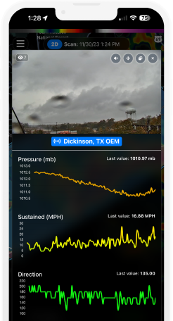
- PTZ camera integration — correlate live video with wind data at every station
- Combined weather picture — wind alongside rain gauge, humidity, temperature, and pressure from the same station
- Remote access — all data and system management accessible from any location via RadarOmega
Who Deploys cyclonePort Wind Monitoring
| Sector | What cyclonePort Enables |
|---|---|
| Emergency Management | Real-time wind monitoring for severe storm situational awareness, NWS coordination, and multi-agency response. Sustained speed and gust data across a distributed network reveals storm structure and intensity at the ground level. |
| Broadcast Media | Live wind observations for on-air storm coverage. Display real measured gusts at specific locations across your coverage area — not airPort interpolations — while events are happening. |
| Utilities & Power | Continuous wind monitoring along transmission corridors for vegetation management timing, PSPS decision supPort, fire weather threshold monitoring, and storm crew staging. |
| Construction Safety | On-site anemometer data for crane operation documentation, lift plan weather verification, and elevated work safety decisions. |
| Schools & Athletics | Real-time wind data as part of a complete weather safety system for outdoor event decisions, athlete protection, and weather policy compliance. |
| Venues & Commercial | Wind speed monitoring for outdoor event safety decisions, facility operations, and documented weather conditions for liability and insurance purposes. |
Deploy Wind Monitoring at Your Site cyclonePort scales from a single station to large multi-location wind monitoring networks. Contact our team to configure the right deployment — hardware, mounting height, telemetry, and platform integration. info@cycloneport.com · 844-737-9328 · cyclonePort.com/contact |
09 Frequently Asked Questions
What is an anemometer and what does it measure?
An anemometer measures wind speed. In many professional weather stations, it is part of an integrated wind sensor that reports wind speed, gust, and wind direction together.
What is the difference between wind speed and wind gust?
Sustained wind speed is an average over a defined time period, while a gust is the highest short-duration wind speed observed within that period.
What is the difference between a cup anemometer and an ultrasonic anemometer?
Cup anemometers use rotating cups and usually a separate vane, while ultrasonic anemometers measure wind electronically without moving parts. Cup systems use less power; ultrasonic systems generally respond faster and need less mechanical maintenance.
What wind speed is dangerous for outdoor operations?
Dangerous wind speed depends on the activity, equipment, site exposure, and safety rules in use. Real-time on-site measurements are often more useful than regional forecasts for operational decisions.
Why does mounting height matter for wind measurement?
How accurate is a professional cup anemometer?
Accuracy depends on the sensor design, calibration, and measurement range, but siting and mounting quality often affect real-world data more than laboratory specifications alone.
Can a cup anemometer be used in cold climates with ice and snow?
Yes, but ice can impair mechanical wind sensors. Heated designs can improve performance in freezing conditions.
What is the standard wind speed reporting format in weather data?
Wind speed may be reported in mph, knots, m/s, or km/h depending on the application. Wind direction is reported in degrees from true north and indicates the direction from which the wind is blowing.
Related Instruments & Guides
Wind direction is one component of the complete cyclonePort weather station. Explore related instrument pages:
↗ Wind Meter & Anemometer — Wind speed, gust measurement, and Beaufort/Saffir-Simpson context
↗ Barometric Pressure Sensor — Pressure trend analysis for front detection alongside directional wind data
↗ Lightning Detection System — Lightning detection integrated with wind direction for complete storm awareness
↗ WBGT Monitor & Heat Stress Sensor — Heat stress monitoring with wind direction context for heat index and comfort
↗ Temperature Sensor — Air temperature monitoring alongside wind chill and heat index calculation
↗ Humidity Sensor & Hygrometer — Relative humidity and dew point with wind direction for air mass characterization
↗ Rain Gauge — Precipitation monitoring alongside wind direction for storm tracking and front passage documentation
Related Instruments & Guides
The anemometer is one of several precision instruments in the cyclonePort weather surveillance system. Explore related instrument pages:
↗ Humidity Sensor & Hygrometer — Relative humidity, dew point, and atmospheric moisture monitoring [link]
↗ Rain Gauge — Tipping-bucket precipitation measurement, accumulation, and intensity monitoring [link]
↗ Barometric Pressure Sensor — Pressure monitoring for storm tracking and weather pattern analysis [link]
↗ Temperature Sensor — Air temperature measurement, heat index, and WBGT calculation [link]






Built for Severe Weather
Remote system management from anywhere
Deploy high-quality PTZ (Pan-Tilt-Zoom) IP cameras designed for effortless setup and immediate operation through plug-and-play simplicity. This advanced design significantly reduces installation time and complexity, making sophisticated surveillance accessible for businesses of all sizes. Multiple cameras connect seamlessly to the network.
Remote system management from anywhere
Deploy high-quality PTZ (Pan-Tilt-Zoom) IP cameras designed for effortless setup and immediate operation through plug-and-play simplicity. This advanced design significantly reduces installation time and complexity, making sophisticated surveillance accessible for businesses of all sizes. Multiple cameras connect seamlessly to the network.
Remote system management from anywhere
Deploy high-quality PTZ (Pan-Tilt-Zoom) IP cameras designed for effortless setup and immediate operation through plug-and-play simplicity. This advanced design significantly reduces installation time and complexity, making sophisticated surveillance accessible for businesses of all sizes. Multiple cameras connect seamlessly to the network.
Remote system management from anywhere
Deploy high-quality PTZ (Pan-Tilt-Zoom) IP cameras designed for effortless setup and immediate operation through plug-and-play simplicity. This advanced design significantly reduces installation time and complexity, making sophisticated surveillance accessible for businesses of all sizes. Multiple cameras connect seamlessly to the network.
Learn From The Field

- Guides
Cal/OSHA Heat Regulations for Outdoor Workers: What California Employers Must Know
- Guides
GCSAA Lightning Safety Guidance for Golf Courses: A Complete Compliance Guide